Conway's game of life on the BLiTTER
 Since I’ve got an Atari Mega 4, I’ve been reading up on the Atari ST Blitter and
what to do with it. Apart from being excellent at copying bitmaps around, it
does have a few cool tricks up its sleeve.
Inspired by Paranoid’s BLiTTER FAQ, I learned that you can do cool things with the halftone pattern registers and the smudge mode of the blitter. Enabling smudge mode basically turns the halftone pattern into a 16 entry lookup table. Paranoid uses that to implement saturated increments and chunky to planar conversions (albeit slightly slower than the fastest m68k solution using movep instructions, it could still be useful in some cases.)
Note: For the rest of this article I assume you have some knowledge of how the Blitter works. I recommend taking a look at Paranoid’s FAQ and Atari’s official docs if you need a brush-up.
Lookup tables means we can approximate some (very rudimentary) calculations. Could something like Game of Life be implemented using the BLiTTER?
The rules are simple. The Wikipedia article on Conway’s Game of Life describes them as thus:
The universe of the Game of Life is an infinite two-dimensional orthogonal grid of square cells, each of which is in one of two possible states, alive or dead, or “populated” or “unpopulated”. Every cell interacts with its eight neighbours, which are the cells that are horizontally, vertically, or diagonally adjacent. At each step in time, the following transitions occur:
- Any live cell with fewer than two live neighbours dies, as if caused by underpopulation.
- Any live cell with two or three live neighbours lives on to the next generation.
- Any live cell with more than three live neighbours dies, as if by overpopulation.
- Any dead cell with exactly three live neighbours becomes a live cell, as if by reproduction.
Now how do we implement this on the Blitter? The Blitter can’t count pixels, or does it?
Let’s assume that the initial pattern is stored in a monochrome bitmap. Initially, the steps I had in mind to generate the next generation constist roughly of these:
- Munge the initial bitmap, copying each pixel to one word per pixel in the original bitmap. (A sort of a reverse chunky to planar conversion.)
- While we’re at it, include info on the pixel to the left and the right of the pixel.
- Merge into the data, the six pixels above and below the current pixel.
- Loop through the extracted pixels a few times, use the smudge mode and halftone patterns to convert the surrounding pixel data into a count of pixels
- Last run through the smudge would combine the current pixel with the pixel counts and the rules of the game to determine whether to write or clear the pixel.
- Convert these wide pixels back to the original bitmap.
- profit!
Here’s what I ran into: There are in total 9 pixels surrounding each pixel, if I wanted to count them using the halftone registers as a lookup table, I can only map 4 pixels at a time. Then, the final count has to fit into 4 bits together with the actual pixel so I can build the decision table. Representing a number from 0 through 9 requires 4 bits, but luckily, we only need to count to 4, as anything higher than 4 has the same result.
I revised my algorithm and describe it in some details below.
1. Count surrounding rows first
I decided it was easier to count the pixels above and below the current pixel first. And that it could be done while looping through the original bitmap. And to top it all, I decided to process two pixels at a time, meaning I could grab four pixels from the rows above and below.
Let’s consider a pixel array like this:
| a0 | a1 | a2 | a3 | … |
| b0 | b1 | b2 | b3 | … |
| c0 | c1 | c2 | c3 | … |
| … | … | … | … | … |
Pixels b1 and b2 have pixels a0, a1, a2, and a3 as their combined upper neighbors (sharing a1 and a2.) If we shift pixels a0 - a3 to the right so they can be used as the halftone lookup entry, we can construct a table like this:
| bit pattern | pixel count (left pixel, right pixel) |
|---|---|
| 0000 | (0,0) |
| 0001 | (0,1) |
| 0010 | (1,1) |
| 0011 | (1,2) |
| 0100 | (1,1) |
| 0101 | (1,2) |
| 0110 | (2,2) |
| 0111 | (2,3) |
| 1000 | (1,0) |
| 1001 | (1,1) |
| 1010 | (2,1) |
| 1011 | (2,2) |
| 1100 | (2,1) |
| 1101 | (2,2) |
| 1110 | (3,2) |
| 1111 | (3,3) |
Munging this into a suitable halftone table, we now loop through the source bitmap and store the partial pixel counts into the temporary buffer. That should give us a table containing the counts for the three pixels above and below. Using a combination of an endmask and encoding the counts as a pair of bits, we can cram the counts into adjacent 4 bits in our buffer.
2. Sum the (still partial) counts
Next we need to sum the counts for the row above and below. Our temporary buffer now contains a pair of counts (2x2 bits) that we want to sum up.
Summing two 2-bit numbers can be done as a lookup using the halftone map. Four bits give us exactly 16 combinations, summing up into a 3-bit sum:
| Bit pattern | sum | final bit pattern |
|---|---|---|
| 0000 | 0 + 0 = 0 | 000 |
| 0001 | 0 + 1 = 1 | 001 |
| 0010 | 0 + 2 = 2 | 010 |
| 0011 | 0 + 3 = 3 | 011 |
| 0100 | 1 + 0 = 1 | 001 |
| 0101 | 1 + 1 = 2 | 010 |
| 0110 | 1 + 2 = 3 | 011 |
| 0111 | 1 + 3 = 4 | 100 |
| 1000 | 2 + 0 = 2 | 010 |
| 1001 | 2 + 1 = 3 | 011 |
| 1010 | 2 + 2 = 4 | 100 |
| 1011 | 2 + 3 = 5 | 101 |
| 1100 | 3 + 0 = 3 | 011 |
| 1101 | 3 + 1 = 4 | 100 |
| 1110 | 3 + 2 = 5 | 101 |
| 1111 | 3 + 3 = 6 | 110 |
The actual values I used in the halftone maps are a bit different in order to control where I want to place the results. Using this map, I perform two passes with the temporary buffer both as the source and destination. (Two passes, as I store information about two pixels in each word.)
3. patch in information about the current row
Let’s assume that each byte in the buffer now contains the sum calculated above shifted left by two bits:
| upper byte | lower byte |
|---|---|
| 000XYZ00 | 000xyz00 |
(where XYZ and xyz are the three bit sums calculated in step 2.)
Now we want to include information about the current row including the pixel itself, so our buffer will contain entries like this:
| upper byte | lower byte |
|---|---|
| 00CXYZAB | 000cyzab |
Where C is the current pixel, and AB is the count of pixels to the right or left of it. We can use a halftone map similar to when counting the pixels above and below, and again, we can process information for two pixels (ie. reading 4 pixels from the current row) at a time.
4. Final sum
Now to add the left and right pixels. We stored that count adjacent to our 3-bit sum, so we can use the same trick as when summing up the upper and lower rows.
But isn’t there is a problem here? We now need to add together a 3-bit and a 2-bit number, and that’s 1 bit too many to handle in a single pass. I figured out that if I only add up the lowest two bits of the initial sum and don’t overwrite the third bit, everything will work as before:
If the initial sum is 4 or larger, we actually don’t need the result from this addition, as according to the rules, when the count is larger than 3, the cell should be cleared. The only corner case is when the final sum would overflow from a number less than 4. In our case, we ignore the third bit and the number will wrap around. Since the number of pixels in the same row can be maximum 2, 2+3 will wrap around to 1 and 2+2 to 0 instead of 5 and 4 respectively (any other combinations will not carry, and we’re therefore safe). We are again saved by the rules, as the result for 0 and 1 neighbors is the same as for 4 and 5.
5. Apply the rules
After that final sum, we now have the current pixel and a 3-bit count in our buffer. We now just need to figure out what the final pixel value should be and write that into the buffer.
I will show here the actual halftone map used in my code:
static const uint16_t game_of_life_rules[] = {
            // patt: cp count result
    0x0000, // 0000:  0 0  -> 0
    0x0000, // 0001:  0 1  -> 0
    0x0000, // 0010:  0 2  -> 0
    0xFFFF, // 0011:  0 3  -> 1
    0x0000, // 0100:  0 4  -> 0
    0x0000, // 0101:  0 5  -> 0
    0x0000, // 0110:  0 6  -> 0
    0x0000, // 0111:  0 7  -> 0
    0x0000, // 1000:  1 0  -> 0
    0x0000, // 1001:  1 1  -> 0
    0xFFFF, // 1010:  1 2  -> 1
    0xFFFF, // 1011:  1 3  -> 1
    0x0000, // 1100:  1 4  -> 0
    0x0000, // 1101:  1 5  -> 0
    0x0000, // 1110:  1 6  -> 0
    0x0000, // 1111:  1 7  -> 0
};
I apply this map twice again to process the upper and lower byte in each word, masking out the writes, so I now have either 255 or 0 in each byte.
6. Copy the results back
Here I simply loop through each word in the buffer and copy the middle two bits back into my source image.
TAH-DAH!

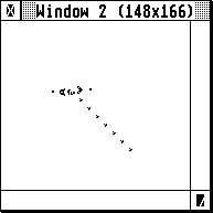
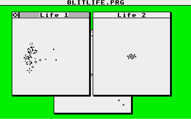
And that’s basically it. I have created a simple (and ugly) GEM application that wraps my blitter algorithm. It hard codes three images and opens each in their own window. Closing all windows will exit the application. If you want to experiment with other patterns, you will have to modify them in the source and recompile the application. Also note that you need an ST with a blitter chip. The code does not test for it and will most probably bomb out if you try to run on a machin without… It may even bomb on a machine with one. ;)
Downloads:
- Source: Github Repository
- Binary: blitlife.prg